Since Tony Hines asked about fitting the Maxon motor into a Kato Mikado, I figured now is the time to split this off from the discussion about molding lead weights and begin a proper project thread on my Mikado. This will be an NP W-5 using a Kato Mikado
and the GHQ W-3 pewter kit. I expect this to be a straightforward kit build with perhaps a few detailing and drivetrain
tweaks, hopefully not a massive scratchbuild.
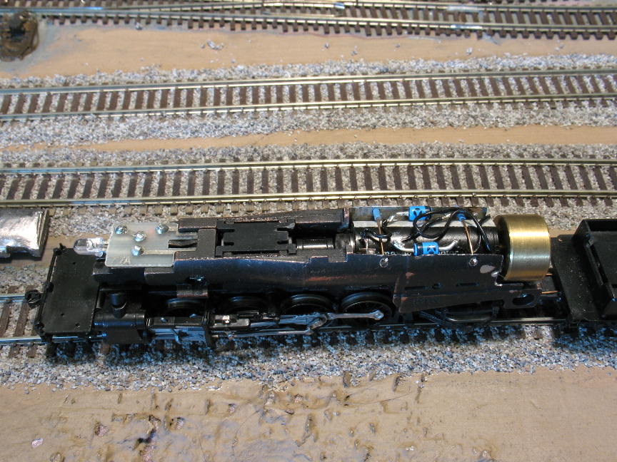
For starters, here is the new Maxon motor fitted into the Mikado chassis. It actually drops right in and aligns with the worm
coupling with no shimming needed! You do have to grind some metal off the inside faces of the frame where the motor goes
in order to make it fit. I pulled out the drivers, gears, valve gear, everything, took the frame halves apart, and
then flat-filed the insides until I got enough clearance for the motor. You could probably do it with a Dremel and a metal grinding bit
without taking the chassis apart, but this makes things neater. Plus, I didn't have to tape everything up to protect against metal shavings in the gears.
The two blue solid state devices are 4.3v 1W zener diodes. I put then back to back, in-line with one lead of the motor.
This drops a fixed 4.3 volts. This is a 12v motor, but it actually starts turning and moving the engine at under 0.5 volt,
which can be very annoying! By knocking 4.3 volts off there, it operates in a more comfortable range for DC,
and the headlight will come on at full brightness before the engine starts to move. If you use a DCC decoder, you can
program the speed steps, I'm sure, to avoid this problem and the diodes wouldn't be necessary. The motor draws so little
current that even a 1/2 watt zener would do the trick. But I had these handy and they are still small.
Also shown: my home-made weight comprised of tungsten plate and lead, weighing 20g vs the stock weight's 10-12g.

Note the big flywhee on the back. That is a 12mm. The original Kato is about 10mm and is much thinner. I had to
grind out some of the frame below the flywheel to allow clearance for it. The trick to getting it onto the backshaft of the Maxon
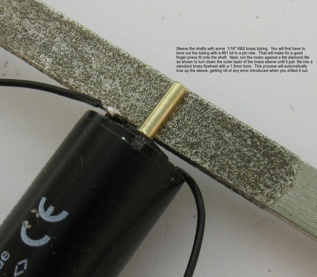
1024 motor was to first sleeve the shaft with some 1/16" OD K&S tubing. It won't fit over the shaft as it. You will need to
drill out the tubing with a #62 bit. Once I pressed it on (just finger tight), I put a drop of green Loctite on the tip to fix it.
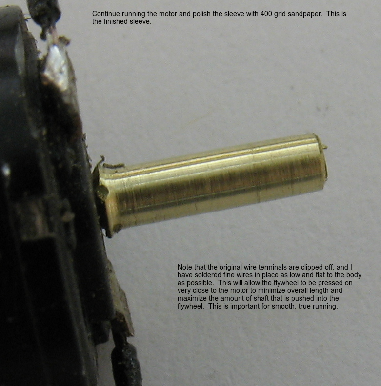
Now, the tubing will actually be TOO BIG to fit inside the flywheel. So I ran the motor and held a file against it, checking frequently until I turned it down to just about 1.5mm to match the flywheel bore.
I prefer to do it this way because I find it a lot easier to get a perfectly true sleeve than to bore out the flywheel and keep it
true. Plus, this way, if there was any error when you bored out the tubing, you will correct it when you turn it down with the file and the flywheel will turn perfectly.
You need to be able to press the flywheel on with your
fingers. The motor shaft cannot tolerate any pushing or twisting. Again, LocTite will fix the flywheel. The trick is to get it snug
so it won't wobble, but not so tight that you need to really "press" it on.
Here's the turning of the shaft sleeving:


Here's some video of the mechanism running.
I put a black mark on the flywheel with a sharpie so you can see how slow it turns. And remember, this one does not
use a gearhead, even though I normally like gearheads.
https://www.youtube.com/watch?v=k25MU0kFZUg