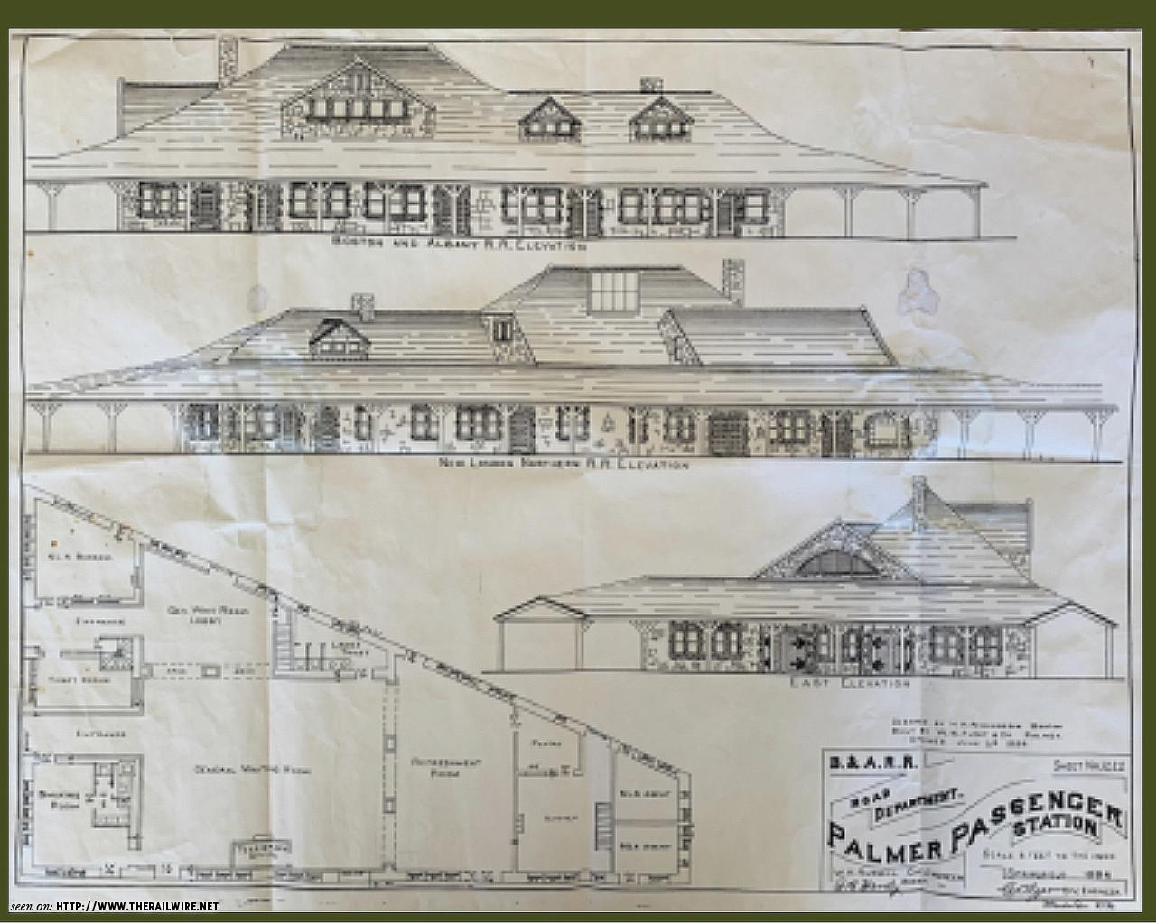
Palmer Union Station, Palmer, MA. I went to an operating session at the Central Vermont in Northern California and decided to get involved with this group. It is a very impressive layout, all designed for operation. Set in May 1956, the layout depicts the Southern Division of the Central Vermont from Palmer, MA to New London, CT. The layout is a work in progress, although much of the scenery is complete. It is missing the signature structure of Palmer Union Station, so I decided to think about how to model this structure. It opened in 1894 and was designed by architect H.H. Richardson in his iconic Richardson Romanesque style. Richardson did several stations for the Boston & Albany. Yes, this is HO, but I am not really going to the dark side.
I had a fuzzy plan and elevations of the station that would be the basis. I also scoured the internet for photos, and found quite a few that would help with the details. I am in California, so no time right now for a site visit. Google Earth image and a Sanborn map where useful to scale the plan and elevations.


I created an HO scale mock-up using the elevations to see how the building would fit on the layout. The space is just large enough to fit a full scale HO station, so it was decided that the building would not be compressed. The fascia will be extended over the lower deck to create more land for the full size station.

The building walls are all granite and sandstone with rustic texture, definitely a modeling challenge. I have access to a high-end laser cutter (Glowforge), although I had never used it. It can both cut and etch. It would cut the walls out and etch stone pattern. For the stone texture, I would use matte medium gel, applied to each stone with a wood skewer. While that may sound tedeus, I have used this technique before on my N scale PRR Sherman's Creek stone bridge which went very well. It had to easier in HO scale, right? I decided to test a small wall section to see if my idea was feasible. With some basic tutorial, I created the file for the laser cutter using Adobe Illustrator. Very simply, all lines to be cut through were done in blue and etched lines are done in red. The file is exported as an .SVG file, and the Glowforge web interface does the rest. The stone pattern was hand drawn on vellum from photographs, and then scanned and dropped into the Illustrator file using the wall outline.

To my amazement, it all worked and I had a test section made from 1/8" MDF board. I started adding the matte medium gel texture to each stone, and it went smoothly. When dry, I painted the wall section gray for the granite stone, and a terra cotta color for the sandstone. I painted a few stones lighter gray as not all of the stones are the same gray value. This test section was definitely a success. Can it translate to the full building? Yes, with patience.
Test sample as it came out of the laser cutter (windows and door not popped out yet).

Adding stone texture with matte medium gel.

The finished test wall section after painting.

The wall section being test modeled.

The next step is to prepare drawing files for the full walls that will be done with the 1/8" MDF board. I will also create separate files for windows layers that will be glued inside the stone walls and probably made from 1/16" board. The distictive doors may be created from scaled photos.

When the walls are complete, I will tackle the complex roof of intersecting planes. I think that will be doable with some measurements from the drawings, and a good amount of test fitting. After the roof is modeled, I will figure the best way to add slate roof texture. This is a challenging project, but so far it has been a fun one. More progress reports later.