As it has been mentioned already, the most likely problem is intermittent contact either between the side pickup strips and the bottom of the decoder or between the motor contacts and the decoder. In my view this is not the best design, but we have to put up with it.
You could determine which of the sets of contacts is intermittent. If the loco doesn't run but you can still control the headlights then the motor contacts are acting up. If everything is dead (headlights and motor) then the pickup contact strips connection is flaky.
There are at least 2 versions of Digitrax DN163K0 decoder and a TCS version. Their motor contacts are slightly different, so I have two different methods of installing them.
The newest revision of the Digitrax DN163K0 decoder has motor contact pads on both sides of the circuit board. As shown in this photo of the bottom of the decoder, those pads are smaller then the ones on top. Those pads are gold plated - that is good for reliable contact.

DN163K0_906.jpg
When installing those decoders I first totally remove the motor and reshape the contacts like this.

DN163K0_904.jpg
Then carefully reinstall the motor back in the cradle threading the contacts through couple of slots which seems like Kato made just for this purpose! Then I bend and trim the contacts as shown in the photo. The length is critical: if they are left too long or too short, they won't make a solid contact with the decoder's motor pads. Then bend them as shown in the photo. This way when the decoder is installed and the motor contacts arepushed down by the decoder, the peak on the strips will contact roughtly at the center of the decoder's pads.

DN163K0_905.jpg
At this point, reinstall the motor in its cradle back into the metal chassis, install the decoder and snap in the plastic snap.
The other decoder type requires another installation method.

DN163K0_901.jpg
First of all,
DO NO USE Kapton tape! I hate using that stuff in this installation, just as much as I hate using duct tape on anything!

The tape adds thickens to the pickup strips, affecting how they contacts the bottom pads of the decoder, plus I don't trust it to keep the contacts separated. I know, it works, but still dont' like it.
With the circuit board removed take a fine-point black Sharpie marker (pencil will also do the job) and mark on the pickup strips areas around the motor contacts. Make the mark wide enough to make sure the motor contacts will not contact the pickup strips. Then take the pickup strips out and using a cutoff wheel in a Dremel tool grind the marked notch in the pickup strips as shown here.

DN163K0_900.jpg
The way I grind the notches is by holding the pickup strip in a pair of small vice grips. I just grab the strip directly under where the notch will be (yes, there is not much metal to hold onto, but I have no problems), then I use a cutoff wheel running at a medium-to-slow speed in a Dremel to grind out the notch.
Then install the decoder and bend the motor contacts as shown here. The bend will create a more positive contact after the gray T-shaped snap is installed. Alternately, these contact can be shortened and soldered to the pads. I recommend using solder sparingly and making the solder joints close to the outside edges of the decoder (so the solder does not interfere with the T-shaped snap).
DN163K0_902.jpg
Install the plastic snap and you should be good to go.
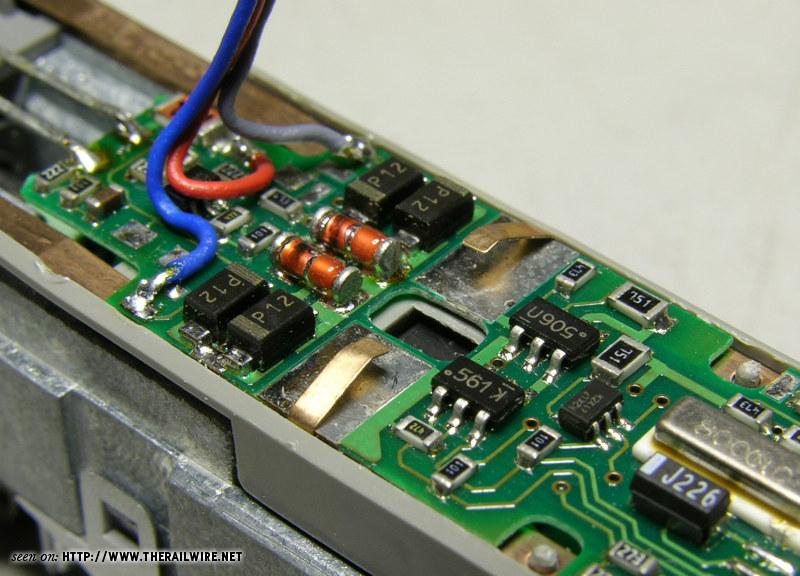
If the pickup strips are still intermittent then like Wutter said, you could solder wire jumpers between the decoder and the strips. This picture shows where to install the jumper wires (purple) on this particular decoder (the other two decoders might be different, but I don't have them handy to show).
A tip when soldering the wire to the pickup strips: When they are still out of the model, pre-tin the areas where the wire will be soldered (you can mark the spot with a sharpie marker when the light board or decoders is still assembled). Those are shown as blue areas on the strips. Then, while still not installed in the model, solder ends of each jumper wire to each pre-tinned area. That eliminates the possibility of melting the gray plastic cradle if the wires were soldered after the installation. Once the pickup strips and the decoder are installed, solder the other ends of the wires to the appropriate spots on the top of the decoder.
(Ignore the red, gray, and blue wires - those are for the ditch ligts.)

DN163K0_903.jpg


