In the process of working on the LL Berkshire, I am working with two examples of the engine.
One has only one powered tender truck and the pickup is flawless (go figure!)
The other (my extensively worked-on one), used to be perfect in the pickup department, with two live tender trucks and some added weight. Inexplicably, it started acting up about 2 days ago. After fussing with it, I finally just
went for a the full frontal assault and did a mod to the trucks that I have done on other
trucks of this type, and thought I'd share the technique here.
These 6-wheel tender trucks are of the well-used design found in the old Concor/Kato Hudson and 4-8-4 S2,
the LL Berk, and even the LL 0-8-0. They come from the era before the axle-point style that we know and love.
Sometimes, you will come across these, and can't readily just ditch the tender or change out the trucks, so what can
be done to make them work better?
First, a look at them, and a little discussion of what's wrong with them.
Here's a truck in the LL Berk tender.
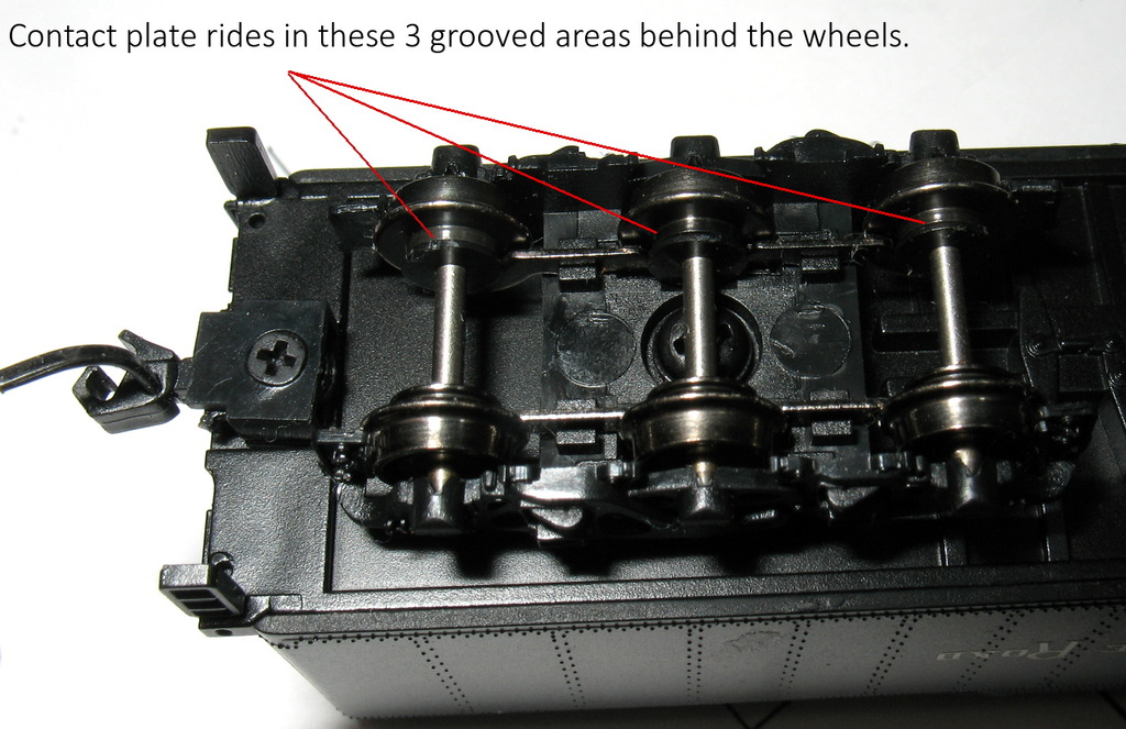
The metal plate rides in those 3 grooves behind the wheelbacks. The plate
has a finger that protrudes up into the tender, and is pressed down by a long thing phosphor bronze strip mounted in the floor, just like the axle-point designs. The finger and the strips are fine. The issue is this rigid metal
plate that rides in the grooves.
It can spring up and down via the strip in the tender floor, but the whole thing has to move up and down as a single unit. True, it can rock slightly from front to back, and that was probably the thinking behind the design, that it would rock fore and aft, allowing the front and back wheel in each truck to somewhat rock and float.
But in a 3-axle truck, what happens to that center wheel? In the Hudson, that axle doesn't really touch the plate much.
It mostly runs like a 4-wheel truck as far as pickup is concerned, and that turns out to be a good idea.
either the fore or aft wheel can bob up and down, and the plate and rock to maintain contact on both wheels.
In the Berkshire, unfortunately, that plate is riding pretty hard on the center wheel. So if the center wheel rises, being right under the finger of the plate, it lifts the pressure of BOTH the outer wheels!
If you place the engine on the track and try to lift that center wheel with the point of an Xacto blade, you'll find that it won't life without lifting the whole tender up. Very bad.
So some of the implementations of this design are better than others. The Kato Hudson was one of the better ones.
The other big flaw in these trucks is that they usually have metal plates that are NOT phosphor bronze. I've see a lot that are brass. The LL Berk are a polished chrome-looking metal. That may or may not work; I don't know. But I do know that phosphor bronze is a king as far as maintaining eletrical contact, not oxidizing, and not deforming from springing around.
-------------------------------------------
So here's what I do with these. First, give up expecting it to conduct on 6 wheels. It doesn't It won't, and it never will. Kato clearly realized this when design that GS4 truck contact with the super extra "finger" for the center wheel.
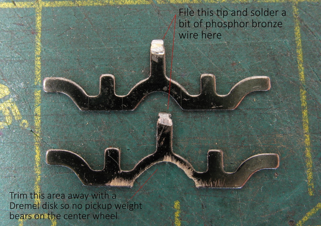
So I grind the plate material out of the way of the center wheel, so that wheel will just spin in there without ever pushing on the plate. I also file a bit off the tip of the finger and solder a bit of phosphor bronze wire on there, so
that the contact with the truck strips will be bronze-to-bronze.
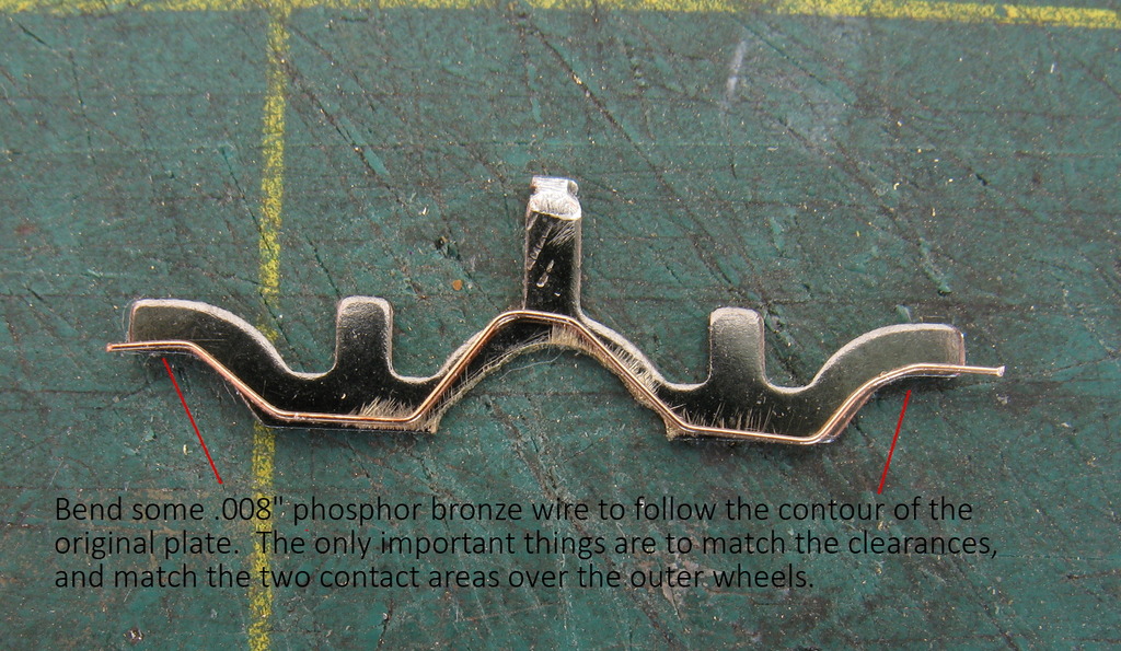
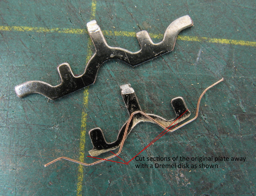
Next, bend a piece of .008" phosphor bronze wire to match the contour of the bottom of the plate.
This will be hard the first time you do it, but I just made two of these today, and they only took me 10 minutes each.
Now, using a Dremel cut-off disk, I just grind off material from the lower edge of the strip. We are going to basically replace that "edge" with the free-floating .008" bronze wire. It doesn't have to be a thing of beauty. Just make sure it's flat and follows the contour without getting in the way of where the wheels have to run.
We also cut away the ends of the plate as shown. You can nip them right off with diagonal cutters.
Now, solder the wire at the center.
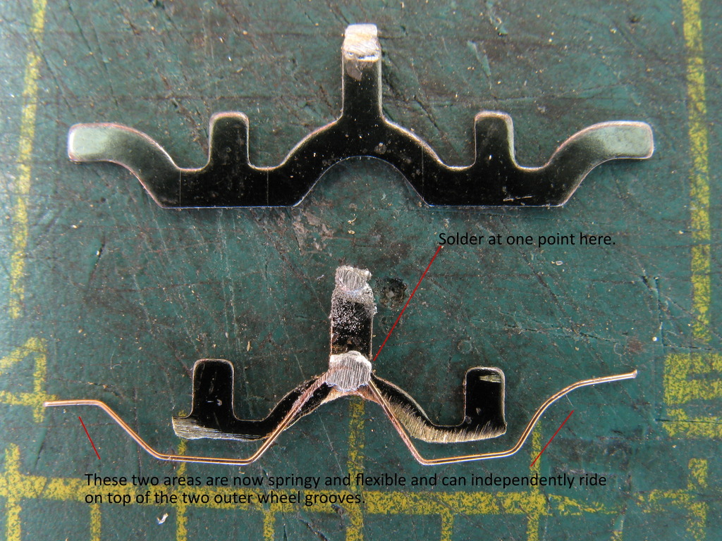
So now we have a plate that is basically the same as before, except that the surfaces that ride in the wheel grooves are phosphor bronze wires that can independently flex and have some spring action to them, instead of having a rigid plate riding against the wheels. And remember, these wires are riding in grooves up behind the wheels, not on the wheel treads themselves, so they tend to stay very clean and reliable. The key here is just changing the metal and adding some spring action.
Install back in the trucks. It sometimes takes some fiddiling and adjusting the wires to get them back in and get the wheels back in with the wires riding in the grooves. But like most things, once you get the hang of it...
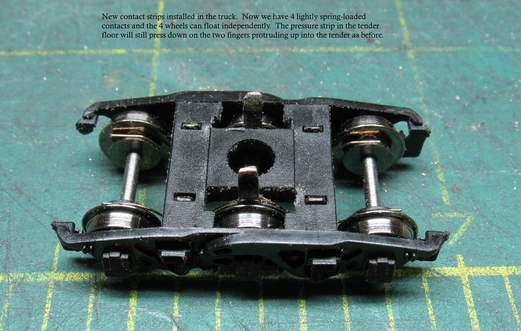
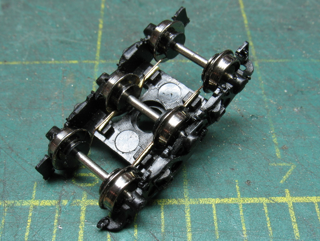
I flipped it on its back, and all 4 wheels tested out fine. Back on the track, the engine runs wonderfully.
=======================================================================
SIDE NOTE about contact, uniform running, and low speed.
This is something that came up in the Backmann Berk discussion, and Victor has alluded to it in there.
When the contact is spotty, the engine may not just make it easy on you and stop. It might run a little herky
jerky. It might just not quite be able to maintain nice uniform motion as it runs. This is because the voltage
is bobbing up and down with the shoddy-but-not-complete-dead contact. I supposed it would be more of an issue
on DC, where you are running an engine at low speed at, say, 3 volts. So if the voltage reaching the motor is
dipping to 2.3, then back to 3, and so on, the engine just doesn't run quite as well.
What I observed in my Berk was that the minimum voltage it would run smoothly at dropped from 3.0 to about 2.5.
That's a big difference. It means running down around 2 mph with good smoothness instead of 3 or 4 mph.
And overall, the engine just plain runs nicer at low speed and it easier to control.


