Hi everyone.
I finally decided to tackle a sound installation in my Atlas Alco C420, and I thought I would share the details since I think this install can easily be adapted to other low-hood diesels. I'm not going to repeat the basic techniques I use in this post; you can refer to my post in The Best of the Wire section of the forum here for more information about how I make my speaker enclosures and other information:
https://www.therailwire.net/forum/index.php?topic=31981.0The installation uses an ESU LokSound Select Micro with the Alco 251 prime mover sound file and an 8 x 12mm speaker in one of my custom sealed enclosures. Here is a short video of the end result:
/>
And here is how I did it.
Because this is a low-hood unit, both the sound decoder and speaker needed to be mounted in the rear of the unit. So the first step was to mill the frame just a bit to make room for the decoder and speaker. This photo is a side view of the milled frame, showing how I sliced off a bit of the top of the center portion of the frame so that the LokSound would fit with a speaker behind it (I also "rounded off" all the sharp edges after making the cut):

To provide for power pickup for the decoder, I used a small piece of the REAR portion of the standard DC circuit board; this piece has one of the surface-mount resistors on it that I will use as a dropping resistor for the front headlight. Though it is cut from the rear portion of the DC board, I am using it in the front of the engine. Notice that I've scraped the traces clean; the left and right traces are where the black and red wires connect; the center trace will be for the white wire to feed the SMT resistor, which in turn will be connected to the negative lead of a 3mm LED for the front headlight:

Now it is time to start wiring the LokSound. One new technique I adopted for this installation was to completely remove the plastic wrap from the LokSound to save some width. I still sanded down the inside of the shell just a tad, but removing the heavy plastic wrap saves about .2mm of width and makes the installation much easier. But because the plastic wrap is gone, you have to be very careful to insulate the LokSound from the frame.
First, I soldered the gray and orange wires to the motor brush leads (the orange goes to the bottom brush) and then put a piece of Kapton tape over this to make sure the LokSound would be insulated from the frame. You will also note that I have added a 3mm sunny white LED at the front; the negative lead of the LED is soldered to the SMT resistor on the piece of circuit board I salvaged for power pickup; the positive lead of the LED will be used for the blue wire connection:

Next, I solder the black, red and white wires to the piece of circuit board. The white wire will go to the circuit board trace leading to the SMT resistor where the LED negative lead is soldered:

The above photo also shows the speaker connected to the brown wires of the decoder. For the rear headlight, I used a surface-mount sunny-white LED that I glued to the rear of the speaker enclosure. You can see the magnet wire running from the rear SMT LED.
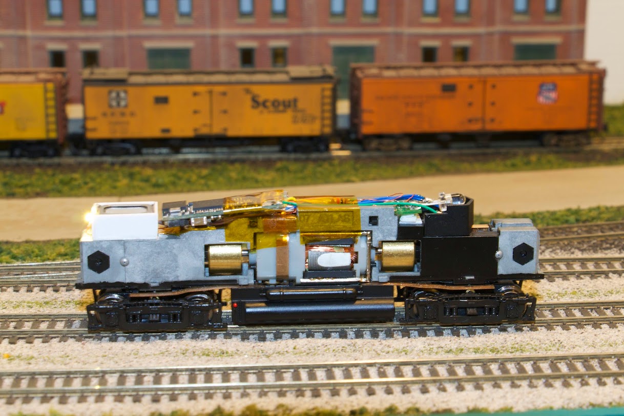
The next photo shows the final placement of the LokSound and the speaker. The magnet wire for the rear LED is routed underneath the speaker and then (along with the speaker wires) underneath the LokSound into the "channel" in the center of the frame. I have also installed a 16v, 220uf tantalum cap under the front LED as a "keeper" cap for this unit. The green wire you see coming from the front and going to the back is a piece of scrap wire soldered to the negative end of the tantalum cap and then to the keeper pad on the LokSound. The blue wire from the decoder is soldered to the positive lead of the front LED, along with the positive lead from the keeper cap (which has to be connected to the blue decoder wire some way) and the positive lead for the rear LED (I twisted the ends of these three wires together, tinned them, and then soldered them to the positive lead of the LED). The yellow wire is soldered to a 1/8-watt 1K resistor, which in turn is soldered to the negative lead for the rear LED. Then I taped down all the wires in the center channel with a piece of Kapton tape:

The next photo is a close-up of the SMT LED for the rear headlight glued to the rear of the speaker enclosure:

The next photo shows the completed chassis sitting on my layout. The rear LED is lit:

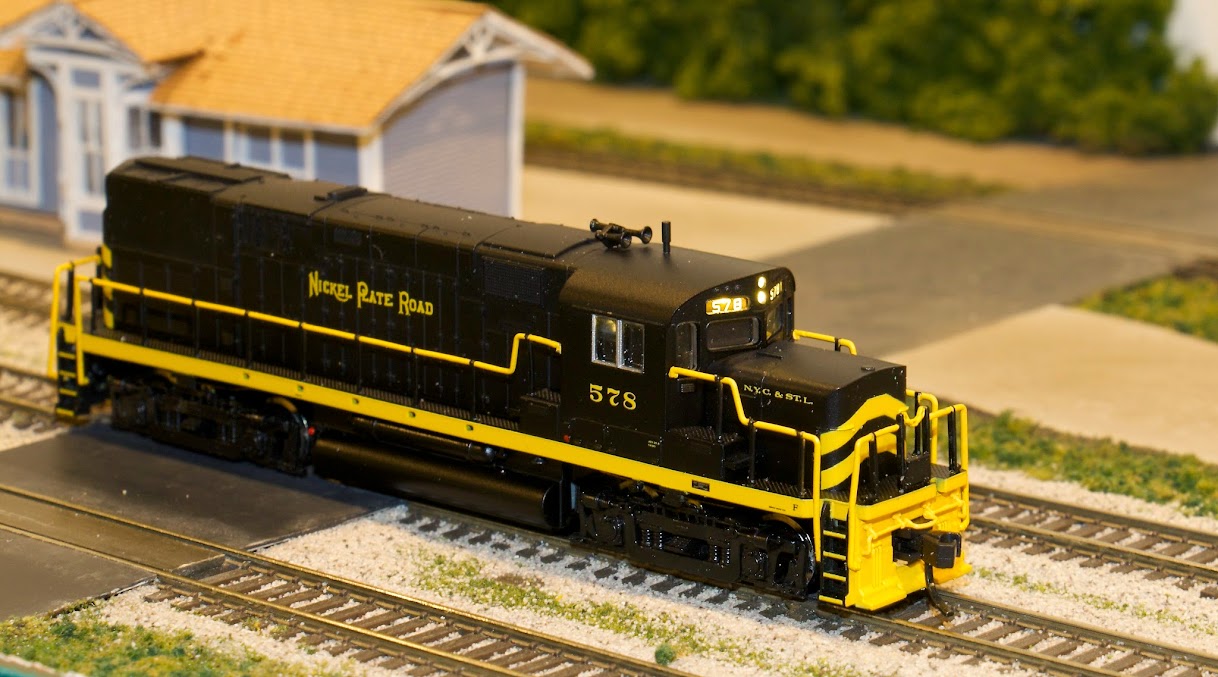
Everything worked, so it was time to put the shell back on. The two photos following show the front and rear headlights with the shell on:


And that's pretty much it.
John C.