Author Topic: Handy CDS photocell detector circuit  (Read 3185 times)

0 Members and 1 Guest are viewing this topic.

mmagliaro

  • Crew
  • *
  • Posts: 6368
  • Gender: Male
  • Respect: +1871
    • Maxcow Online
Handy CDS photocell detector circuit
« on: April 02, 2014, 04:47:43 PM »
0
Simple photodetection circuits based on photoresistors (CDS cells) have been around forever.
However, one of the things that has always been a drawback to them is that they are fussy about having enough
light on the photocell to keep the circuit "off".  That is, if you put a CDS cell down in the track ties, so that
it will be shadowed by a passing train to trigger something "on", you will find that when you turn down the room
lighting, perhaps for night running, the CDS cell gets dark enough that it falsely triggers your detection circuit.

The problem is that CDS cells change their resistance over a VERY wide range from full dark to full bright.
So in the afternoon, your cell might swing from 2k ohms bright to 40k ohms dark,
whereas at night, or for night running, it might be 12k ohms "bright" (uncovered)  to 150k ohms dark.

I was about to just abandon the whole thing, rip the CDS cells out of the ties, and work out something with an IR emitter/detector
or some other means of reliable detection.  But a little experimenting showed me that this isn't necessary.  Below is a circuit that solves the problem, along with explanatory text.

This circuit allow you to have any number of photocells as detectors.  If any ONE of them is covered, the load will switch on.
This is what I needed for a crossing flasher, where I have 2 tracks, and a CDS cell on each side, so there are 4 cells, and I want
the lights to trip on if any one cell is covered.   The prepackaged detector (from Berkshire Junction) tells you to just wire all 4
cells in series.  While this works, it is terrible in dim light.  All 4 CDS cells are lit dimly enought that together they create a high
resistance and falsely turn on the flasher.  What is needed is to have the 4 CDS detections be independent.

Before going any further, I realize that you could do this with logic gates and other methods.
But I've got boatloads of small transistors and other such cheap, simple parts.  They are easy to solder up, very robust,
will work on almost any supply voltage.  This whole thing, for 4 detectors, fits on a little 2" x 2" perfboard.

This schematic shows the circuit for 2 cells.  You just replicate the section (R1,R3,Q3,Q4) and connect to the same points
as that section to get more detectors.
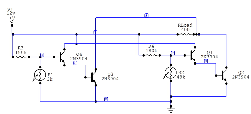


1. What does the circuit do?

Let's focus on the right-hand section detector only.
When photocell R2 is bright, it's resistance is low (say, about 2k).  That is low enough that nearly all the current flowing through R4
goes through R2 to ground and Q1 does not turn on.  We are effectively shorting out Q1's base.
When R2 is darkened, it's resistance goes up.  In the diagram, I have it at 48k.  At about 20k, enough current flows through Q1's base to turn it on.  Q1 amplifies this tiny current, feeding the larger current to Q2's base, and Q2 will fully turn on (saturate). 
Now, current flows from the +12v through the load (Rload) to Q2's collector, and your load is energized.
The load can be anything, a lamp, some LEDs, a small relay, whatever.   The 400 ohm load in my case was chosen for a
small DPDT relay, but actually, I'm not using a relay there, I am just turning on my flasher circuit.

IF YOU USE A RELAY, be sure to connect a diode across the relay coil in the opposite direction so that when the relay turns
off, the spike that occurs as the relay coil field collapses doesn't destroy Q2.

2. The other detector:
The same behavior occurs in the left-hand side of the circuit.  So if either CDS cell is dark, Q2 or Q3 will turn on and the load
will be turned on.

3. Interaction?
No, there isn't any.  No matter how many stages you build, if any CDS cell is darkened, that leg will conduct enough current to
the transistor base, which will turn on its other transistor and power the load.

4. Adjustment:
It would be best to make R3,R4 potentiometers, not fixed 180k resistors, so you can have some adjustment of the turn-on behavior.

What's so special about it?
After all, it's just a simple 2-transistor switch ain't it?
Well, yes, which is why I'm surprised I didn't find it looking around the web for circuits on CDS detection.
I thought that surely, this wouldn't work all that well, that there must be something else I wasn't thinking of.

The key is that by using two transistors, you only need a very tiny current into the base of Q1 in order to fully saturate and turn on
Q2.   It's like a lever.  So while the CDS cell has a broad range of resistance, I don't care.  When it crosses over certain
value (about 24k in this case), Q1 turns on a "little", Q2 turns on fully, the load is on, and we're all done.

In my case, the CDS cell is about 2k bright, 40k dark in the daytime, and  12k bright, 150k dark in an almost-dark room for night
running.   So what I need is for the this thing to trigger at a resistance between 12k and 40k.
For reliability and variability in room lighting, this circuit as shown triggers when the CDS cell is at about 24k ohms.

The sharp "knee" in the turn-on behavior is the whole beauty of it.   At 24k, the load is fully on.  At 20k, it is off.
That's a VERY narrow range of operation for a photocell - you usually can't make them behave that well.

« Last Edit: July 02, 2017, 12:32:04 PM by mmagliaro »

Philip H

  • Crew
  • *
  • Posts: 8910
  • Gender: Male
  • Respect: +1655
    • Layout Progress Blog
Re: Handy CDS photocell detector circuit
« Reply #1 on: April 02, 2014, 08:34:06 PM »
0
Interesting idea. Can't wait to see it in action.

It does sway something about how many LEOs I know that my initial thought on "CDS" was Controlled and Dangerous Substance. :facepalm:
Philip H.
Chief Everything Officer
Baton Rouge Southern RR - Mount Rainier Division.


mmagliaro

  • Crew
  • *
  • Posts: 6368
  • Gender: Male
  • Respect: +1871
    • Maxcow Online
Re: Handy CDS photocell detector circuit
« Reply #2 on: April 03, 2014, 12:32:35 AM »
0
Interesting idea. Can't wait to see it in action.

It does sway something about how many LEOs I know that my initial thought on "CDS" was Controlled and Dangerous Substance. :facepalm:

Oh yes, I should have said.
I have actually built this and tested it, with 3 detectors so far.  I am building the 4th tonight.
It works exactly as I had hoped.  In bright room light with sun coming through the blinds, or at night, with all the lights off except
some very faint overhead dimmers for nighttime running, the circuit does not trigger until a car goes over one of the photocells.
With the old series wiring, and with the photocell circuits I have used in the past, I always had to find some excuse to
put a streetlamp or some other on-layout light located right near the photocell to keep it from falsely triggering on in dim light.

It does occur to me that it might be a good idea to wire a good-sized electrolytic capacity between Q1 and ground (and Q2, and its other analogous counterparts), so that as a train passes over the detector, if there is a moment where the light sneaks between the cars,
the circuit won't trigger off right away.  The cap would add a little "keep alive" delay so the circuit would stay triggered on for
a second or two after the detection is cleared to avoid this "bounce".  So far, I don't ever see such a problem.  But it still might
be a good idea.

Philip H

  • Crew
  • *
  • Posts: 8910
  • Gender: Male
  • Respect: +1655
    • Layout Progress Blog
Re: Handy CDS photocell detector circuit
« Reply #3 on: April 03, 2014, 08:44:52 AM »
0
We want video . . . . :tommann:
Philip H.
Chief Everything Officer
Baton Rouge Southern RR - Mount Rainier Division.


mmagliaro

  • Crew
  • *
  • Posts: 6368
  • Gender: Male
  • Respect: +1871
    • Maxcow Online
Re: Handy CDS photocell detector circuit
« Reply #4 on: April 03, 2014, 12:43:52 PM »
0
We want video . . . . :tommann:

Ugh... okay okay.  I'll try to do some video later today or tonight so you can watch the train go by and the lights come on.

All 4 are in and working now.

Here's a photo of the completed board installed under my benchwork.  I just built it on copper-plated perfboard.  I wasn't going to
bother working out a printed circuit etch and etching this for a one-shot deal with such few components.  You can see
the 4 identical pairs of transistors.  I did use a 150k fixed resistor + a 100k trimmer in place of the 180k resistor shown on
the schematic, so I have a little adjustment control on how much light it takes to turn the thing off.  Yet another plus.
Since there are 4 independent detectors, you have 4 adjustments, one for each photocell.  This can be important because
in a typical room, the 4 cells around a road crossing could well be exposed to very different light levels depending on
what's in the room.


« Last Edit: July 02, 2017, 12:31:29 PM by mmagliaro »

peteski

  • Crew
  • *
  • Posts: 32955
  • Gender: Male
  • Honorary Resident Curmudgeon
  • Respect: +5340
    • Coming (not so) soon...
Re: Handy CDS photocell detector circuit
« Reply #5 on: April 03, 2014, 03:44:58 PM »
0
What you have created is sort of a logic NOR gate.  Any "H" (high) level input causes the output to go "L" (low).  Like you said, this could easily be accomplished (with much lower component count and less soldering) with an integrated circuit (CMOS logic).  There are gates available which have Schnott Trigger inputs which would condition the voltage fluctuations on the input.  You would still have to use a single transistor on the output (to provide sufficient output current), but overall, the circuit would be much simpler.

Having bunch of spare transistors and resistors would not sway me to build this circuit, when I could accomplish the same with a 14-pin IC available new for about 50 cents.  But that's me.

Using discrete transistors is so 1970s...    I'm not knocking your design - it is a working solution - just rolling my eyes.  :)
. . . 42 . . .

mmagliaro

  • Crew
  • *
  • Posts: 6368
  • Gender: Male
  • Respect: +1871
    • Maxcow Online
Re: Handy CDS photocell detector circuit
« Reply #6 on: April 03, 2014, 04:08:16 PM »
0
What you have created is sort of a logic NOR gate.  Any "H" (high) level input causes the output to go "L" (low).  Like you said, this could easily be accomplished (with much lower component count and less soldering) with an integrated circuit (CMOS logic).  There are gates available which have Schnott Trigger inputs which would condition the voltage fluctuations on the input.  You would still have to use a single transistor on the output (to provide sufficient output current), but overall, the circuit would be much simpler.

Having bunch of spare transistors and resistors would not sway me to build this circuit, when I could accomplish the same with a 14-pin IC available new for about 50 cents.  But that's me.

Using discrete transistors is so 1970s...    I'm not knocking your design - it is a working solution - just rolling my eyes.  :)

I figured you, or somebody, would essentially say that.   Maybe that's why I like building circuits this way.
Unless the transistor count starts getting ridiculous (like, if I had needed 10, or even 5 per detector, to build this)
I would not have done it like this. 

I'm not so sure about your presumption on the component count.  You'd still a trimmer on each input for adjustment, and you would still have the photocells.   You could get rid of the 8 transistors (in this 4-channel case) and replace them with a chip, but then... we are talking about saving maybe a dozen solder connections?    The scale of this is small enough that it hardly matters.

1970s... heh heh... My throttle is a 1970s design with all discrete components.  Heck, we're not building computers here.
These are simple switches and current amplifiers.

Discrete transistors are cool.  Embrace them.

peteski

  • Crew
  • *
  • Posts: 32955
  • Gender: Male
  • Honorary Resident Curmudgeon
  • Respect: +5340
    • Coming (not so) soon...
Re: Handy CDS photocell detector circuit
« Reply #7 on: April 03, 2014, 04:19:31 PM »
0

Discrete transistors are cool.  Embrace them.

I do - very much so. But only as needed.  :)
. . . 42 . . .

C855B

  • Crew
  • *
  • Posts: 10869
  • Respect: +2417
Re: Handy CDS photocell detector circuit
« Reply #8 on: April 03, 2014, 04:37:27 PM »
0
... Schnott Trigger inputs ...

Hey, Pete... you pull this one out of your... uh... ???  :lol:

https://en.wikipedia.org/wiki/Schmitt_trigger

You may have crossed the name up with: https://en.wikipedia.org/wiki/Schottky_diode
...mike

http://www.gibboncozadandwestern.com

Note: Images linked in my postings are on an HTTP server, not HTTPS. Enable "mixed content" in your browser to view.

There are over 1000 images on this server. Not changing anytime soon.

DKS

  • The Pitt
  • Crew
  • *
  • Posts: 13424
  • Respect: +7026
Re: Handy CDS photocell detector circuit
« Reply #9 on: April 03, 2014, 04:49:07 PM »
0
Interesting. About two decades ago I built a similar circuit consisting of one transistor, a pot, a capacitor and a reed relay to do about the same thing. I used it for building light control: as the room lights dimmed from full mid-day brightness to midnight darkness, a bank of 20 photodetectors would bring on city lights in a pseudo-random pattern thanks to the slightly randomized pot settings. Using reed relays allowed me to control any type of lights regardless of their voltage or load requirements, and the bank of detector circuits had their own supply.


These days I've gotten really lazy, and for crossing signals or similar devices triggered by a passing train, I'd likely use a proximity detector with built-in logic and output amplification. One part; just give it some juice and it does the rest.

...Schnott Trigger inputs...

AAAHHHAHAHAHAHAHAH!

Useful for setting sneeze thresholds, perhaps...
« Last Edit: April 03, 2014, 05:15:18 PM by David K. Smith »

peteski

  • Crew
  • *
  • Posts: 32955
  • Gender: Male
  • Honorary Resident Curmudgeon
  • Respect: +5340
    • Coming (not so) soon...
Re: Handy CDS photocell detector circuit
« Reply #10 on: April 03, 2014, 05:07:32 PM »
0
ROTFL!  My I and M fingers jumped the keys. You guys made me laugh do hard that I cried!
I can't take the credit for this - it was a purely unintentional typo, but wicked funny!

. . . 42 . . .

mmagliaro

  • Crew
  • *
  • Posts: 6368
  • Gender: Male
  • Respect: +1871
    • Maxcow Online
Re: Handy CDS photocell detector circuit
« Reply #11 on: April 03, 2014, 06:22:45 PM »
0
ROTFL!  My I and M fingers jumped the keys. You guys made me laugh do hard that I cried!
I can't take the credit for this - it was a purely unintentional typo, but wicked funny!

I knew what he meant, so I just let it go... Funny!

David,
That is a cool idea for randomly turning on the banks of structure lights!  One question:  The photocell darkens,
the transistor base current rises, the transistor turns on, and the lights come on.  What does the capacitor do?
Do you have it across the base and ground to reduce any on/off chatter when the light is on the hairy edge of turning
on the circuit?
« Last Edit: April 03, 2014, 06:26:38 PM by mmagliaro »

DKS

  • The Pitt
  • Crew
  • *
  • Posts: 13424
  • Respect: +7026
Re: Handy CDS photocell detector circuit
« Reply #12 on: April 03, 2014, 06:30:22 PM »
0
What does the capacitor do? Do you have it across the base and ground to reduce any on/off chatter when the light is on the hairy edge of turning on the circuit?

Yes, exactly. Poor-man's Schnott Trigger.

(Face it, Peteski, you've unintentionally invented a new technical term...)
« Last Edit: April 03, 2014, 06:40:22 PM by David K. Smith »

peteski

  • Crew
  • *
  • Posts: 32955
  • Gender: Male
  • Honorary Resident Curmudgeon
  • Respect: +5340
    • Coming (not so) soon...
Re: Handy CDS photocell detector circuit
« Reply #13 on: April 03, 2014, 07:32:31 PM »
0
Yes, exactly. Poor-man's Schnott Trigger.

(Face it, Peteski, you've unintentionally invented a new technical term...)

Oh yeah, I like it!   :D
. . . 42 . . .

Philip H

  • Crew
  • *
  • Posts: 8910
  • Gender: Male
  • Respect: +1655
    • Layout Progress Blog
Re: Handy CDS photocell detector circuit
« Reply #14 on: April 03, 2014, 08:45:41 PM »
0
Oh yeah, I like it!   :D

Good because that one needs to go in the Railwire Inside Joke thread.
Philip H.
Chief Everything Officer
Baton Rouge Southern RR - Mount Rainier Division.