Simple photodetection circuits based on photoresistors (CDS cells) have been around forever.
However, one of the things that has always been a drawback to them is that they are fussy about having enough
light on the photocell to keep the circuit "off". That is, if you put a CDS cell down in the track ties, so that
it will be shadowed by a passing train to trigger something "on", you will find that when you turn down the room
lighting, perhaps for night running, the CDS cell gets dark enough that it falsely triggers your detection circuit.
The problem is that CDS cells change their resistance over a VERY wide range from full dark to full bright.
So in the afternoon, your cell might swing from 2k ohms bright to 40k ohms dark,
whereas at night, or for night running, it might be 12k ohms "bright" (uncovered) to 150k ohms dark.
I was about to just abandon the whole thing, rip the CDS cells out of the ties, and work out something with an IR emitter/detector
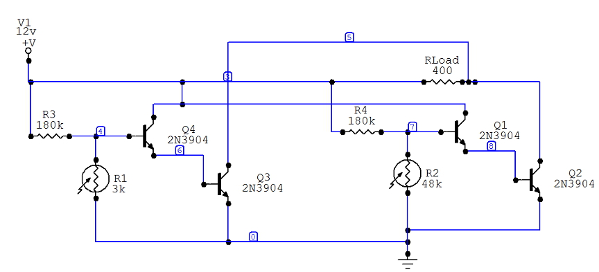
or some other means of reliable detection. But a little experimenting showed me that this isn't necessary. Below is a circuit that solves the problem, along with explanatory text.
This circuit allow you to have
any number of photocells as detectors. If any ONE of them is covered, the load will switch on.
This is what I needed for a crossing flasher, where I have 2 tracks, and a CDS cell on each side, so there are 4 cells, and I want
the lights to trip on if any one cell is covered. The prepackaged detector (from Berkshire Junction) tells you to just wire all 4
cells in series. While this works, it is terrible in dim light. All 4 CDS cells are lit dimly enought that
together they create a high
resistance and falsely turn on the flasher. What is needed is to have the 4 CDS detections be
independent.
Before going any further, I realize that you could do this with logic gates and other methods.
But I've got boatloads of small transistors and other such cheap, simple parts. They are easy to solder up, very robust,
will work on almost any supply voltage. This whole thing, for 4 detectors, fits on a little 2" x 2" perfboard.
This schematic shows the circuit for 2 cells. You just replicate the section (R1,R3,Q3,Q4) and connect to the same points
as that section to get more detectors.

1. What does the circuit do?
Let's focus on the right-hand section detector only.
When photocell R2 is bright, it's resistance is low (say, about 2k). That is low enough that nearly all the current flowing through R4
goes through R2 to ground and Q1 does not turn on. We are effectively shorting out Q1's base.
When R2 is darkened, it's resistance goes up. In the diagram, I have it at 48k. At about 20k, enough current flows through Q1's base to turn it on. Q1 amplifies this tiny current, feeding the larger current to Q2's base, and Q2 will fully turn on (saturate).
Now, current flows from the +12v through the load (Rload) to Q2's collector, and your load is energized.
The load can be anything, a lamp, some LEDs, a small relay, whatever. The 400 ohm load in my case was chosen for a
small DPDT relay, but actually, I'm not using a relay there, I am just turning on my flasher circuit.
IF YOU USE A RELAY, be sure to connect a diode across the relay coil in the opposite direction so that when the relay turns
off, the spike that occurs as the relay coil field collapses doesn't destroy Q2.
2. The other detector:
The same behavior occurs in the left-hand side of the circuit. So if either CDS cell is dark, Q2 or Q3 will turn on and the load
will be turned on.
3. Interaction?
No, there isn't any. No matter how many stages you build, if any CDS cell is darkened, that leg will conduct enough current to
the transistor base, which will turn on its other transistor and power the load.
4. Adjustment:
It would be best to make R3,R4 potentiometers, not fixed 180k resistors, so you can have some adjustment of the turn-on behavior.
What's so special about it? After all, it's just a simple 2-transistor switch ain't it?
Well, yes, which is why I'm surprised I didn't find it looking around the web for circuits on CDS detection.
I thought that surely, this wouldn't work all that well, that there must be something else I wasn't thinking of.
The key is that by using two transistors, you only need a very tiny current into the base of Q1 in order to fully saturate and turn on
Q2. It's like a lever. So while the CDS cell has a broad range of resistance, I don't care. When it crosses over certain
value (about 24k in this case), Q1 turns on a "little", Q2 turns on fully, the load is on, and we're all done.
In my case, the CDS cell is about 2k bright, 40k dark in the daytime, and 12k bright, 150k dark in an almost-dark room for night
running. So what I need is for the this thing to trigger at a resistance between 12k and 40k.
For reliability and variability in room lighting, this circuit as shown triggers when the CDS cell is at about 24k ohms.
The sharp "knee" in the turn-on behavior is the whole beauty of it. At 24k, the load is fully on. At 20k, it is off.
That's a VERY narrow range of operation for a photocell - you usually can't make them behave that well.