Time to make the wiring harness. This is a bit time consuming and tedious, but I think it is worth it for the reasons described above.
The key parts that make all this happen and feasible are some micro-miniature plugs that I came across.
I have ALWAYS been interested in tiny connectors to better facilitate my kitbashing. In fact I just bought some last August when I was in a hobby shop in Georgia.
Unfortunately, sort of like the Holy Grail.... I never quite find what I want.
That is until I discovered these from Train Control Systems (TCS).
Disclaimer: I don't work for TCS or have any connection to them at all. But as most of you who know me, I do tend to like their decoders and have written quite a number of installation instructions for them.
They call them Micro-connectors.
http://www.tcsdcc.com/public_html/Customer_Content/Products/Supplies/Connectors/Micro_Conn/index.htmlI will admit to you, they are a little pricey- but man are they ever small.
For this project, I also had to make an order with Digikey (for the copper coated fiberglass board on page 1). I searched and searched Digikey for a connector this small and failed. I then even used the Online chat with a Digikey employee- and failed.
I don't know who TCS's supplier is, but these connectors are REALLY small- and perfect for N scale applications.
(other people are welcome to post what you use as connectors. Either your experiences with these from TCS or something else).
OK. First we need a place to mount all this stuff.
I took some heat shields out of my parts box and they worked perfectly.
Atlas still has them. They are the heat shields for the old Atlas/Kato/Japan RS-1 (not China, and the heat shield for the old U25B is similar, but does not have a key part- the lip).
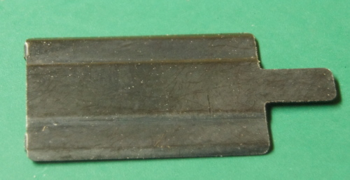
The heat shield is made of steel and sticks to the motor magnets. I like to position it so that the right edge is INSIDE the inner edge of the motor frame.
As shown here.
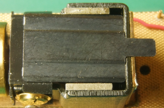
I then hold it firmly in place and bend the little tab on the outside edge..
(I'm not doing a very straight job because I'm using two hands and taking photos with a bulb in my mouth.. lol).
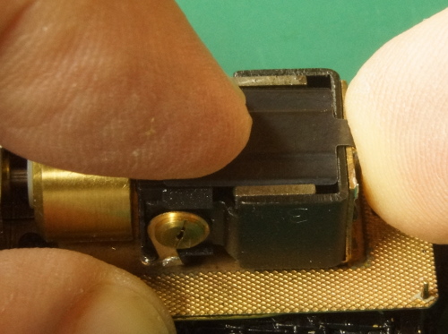
OK. It is bent. This is the basic position I want.
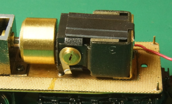
But that bend is not very sharp. I'll use some pliers to make it more of a 90 degree angle instead of a sharp curve- like here.
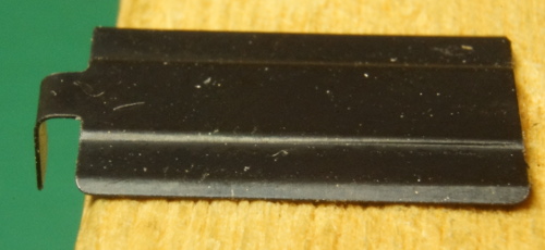
A good fit for that bend is key-- since that will be our connection for transmitting electricity. Remember, in almost all Kumata locos, the frame is hot. So we are going to use that to our advantage in this loco.
Electricity will come from the left rail to the frame, and then to the heat shield that is touching the motor mount L-bracket.
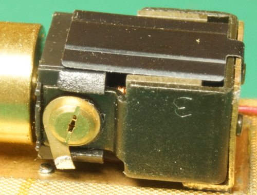
The next step is to scratch some paint off in the corner as shown.
I try to score the metal pretty good but yet keep my area pretty small.
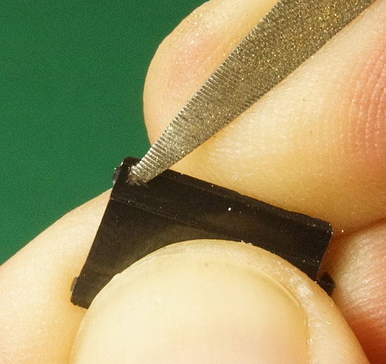
I don't go all the way to the edge. This is a good spot.
I place it on a piece of wood. Flux it and solder it (tin it). I get it pretty hot.
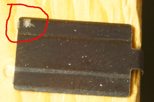
Now, I have to admit to you that this step sort-of surprised (and pleased) me.
1. This plate must be steel since the magnets hold it.
2. I didn't think common solder would stick to steel.
3. But I'm telling you, that little blob does not appear to be going anywhere. I pushed and scraped at it with a screwdriver, and it is stuck.
So, I'm sure some of you guys can add info or insight here.
Either you CAN solder to steel (and I was mistaken) or this little plate is an alloy with steel in it.
(or it is made of some other metal that both sticks to magnets and can be soldered-- sorry this is out of my area of expertise).
All I know is it appears to work.
We can now get electricity from the frame to where we want it to go.
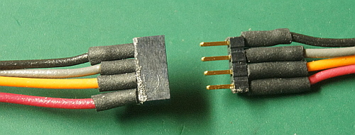
Here is a TCS 4-wire micro plug set. I went with the DCC color set. They also sell them in plain back and white.
And yes, as Peteski said, I have DCC in mind the whole way.
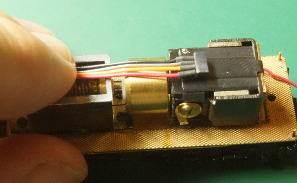
I'm getting an idea of where to mount this. The 4 plug socket will go about in the middle. I want it near the left edge so it can plug in from the right. But the wires cannot obstruct the flywheel.
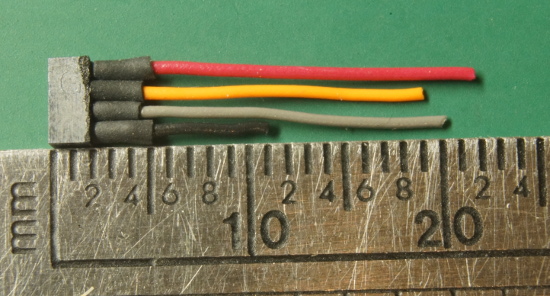
I cut the socket wires to these lengths. You can see the size of the socket here. It is about 2mm x 3mm.
I solder the black wire first since I don't want to melt anything else.
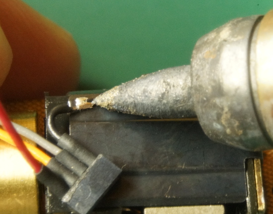
They gray then goes over the black and down to the left motor tab.
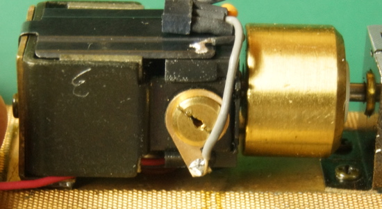
I lift the red wire up slightly and pass the orange under it and down to the right motor tab.
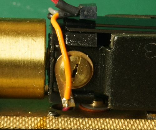
I'll deal with the red wire next time. It is the "problem wire." If I want to be modular, I don't want to solder the red plug wire to the red wire going down to the front truck-- because I would then not be able to get the motor out without unsoldering said connection.
I need a different plan.