Now it is time to turn our attention to the power truck.
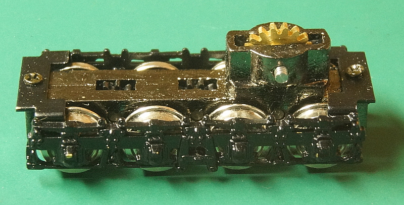
This is one of the more exciting aspects of this new model.
The old NJ 83 version only had two powered axles per truck- and all of the weight was not even on those two axles. They ran terribly.
But these new trucks have all 4 axles powered. Weight distribution is no longer an issue at all.
In the kit, the truck came fully assembled. But here is where potential benefit can come in.
Most of the friction in this loco is in these power trucks. So if I can lower friction in any little ways possible, it might add up to big returns.
Spinning the crown gear (or main drive gear) can give a subjective "feeling" for how the truck is working. It feels a little stiff.
Also, if you place the truck on track and merely push it with your finger from the end (not top), then the truck will SLIDE along the rails and the gears and wheels will not move.
Remember this for when we are finished.
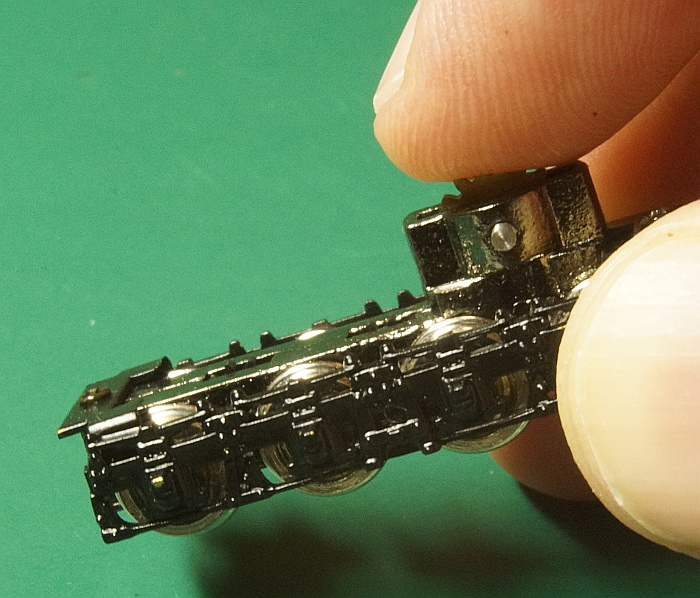
Disassemble the truck by removing the headless screw in the geartower, and the four small screws that hold the bottom cover plate and the sideframes.
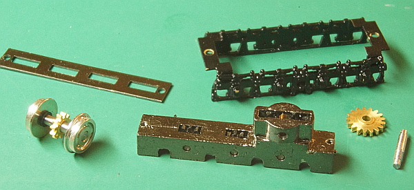
But we need to COMPLETELY disassemble this truck. Those pins need to come out with their transition gears.
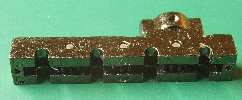 VERY IMPORTANT!
 These pins should be treated as if they only go ONE way. If you push them out one way and then insert them back another way, then the frame metal will be stretched a bit and the pin will be loose.
If you study the frame and pins carefully, you can figure out which way they went in.
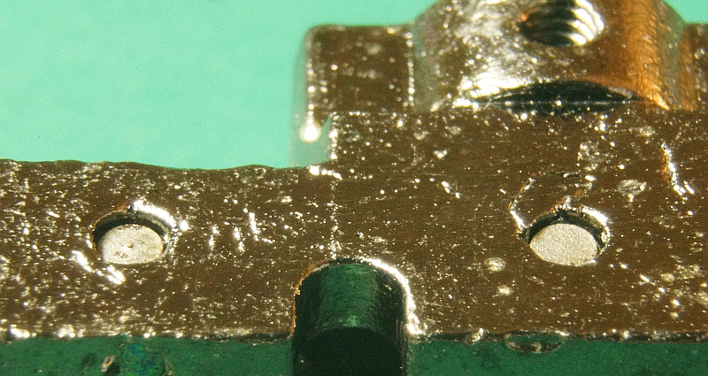
In the photo above, note that there is a little hollow at each pin.
Now look at the other side.
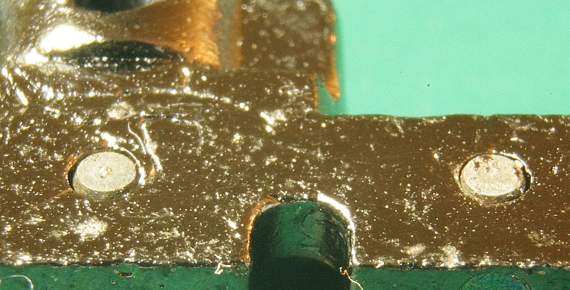
On this side they are flat---- even with the frame.
So
THIS side is the side that the pins were beaten in.
So we want to press them out from the side with the hollow!
But if we are not careful, we will loose track of what we are doing. So I make a mark on the side that I will insert them back. (the even side).
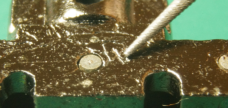
A little fuzzy, but you can see my tiny X.
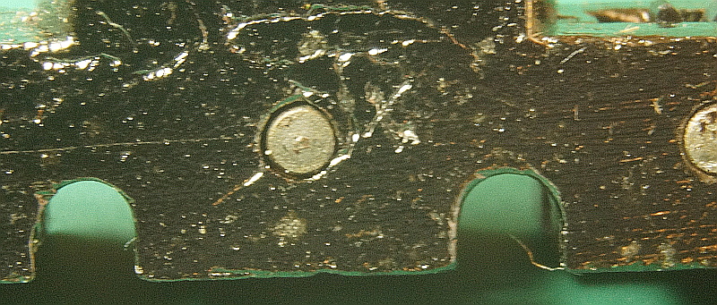
Some specialized tools will help.
Obviously a NWSL puller could possibly press out these shafts- but I find it is cumbersome for this application.
So I made my own tool.
I took a 2x2 piece of wood from a leftover portion of a layout module leg. Square ends helps.
I then mounted a T nut in one end. I drilled the large hole for the center section just deep enough for the metal and then mounted a big long screw to hold it down.
I then found a drill bit that matched the little hole almost perfectly and drilled it fairly deep. This is the receptacle for my shafts. They can drop in.
The punch was an old Dremel bit. I think this one had a little tiny ball on it. I cut the ball off with a ceramic disc. I like this bit/punch because it has such a sharp taper.
I can now use a little brass hammer that I got cheaply from Harbor Freight and beat shafts out of worms (I do that a lot) or here in this case.... to get those pins out of the gearcase frame. Remember, I'm working on the HOLLOW end.
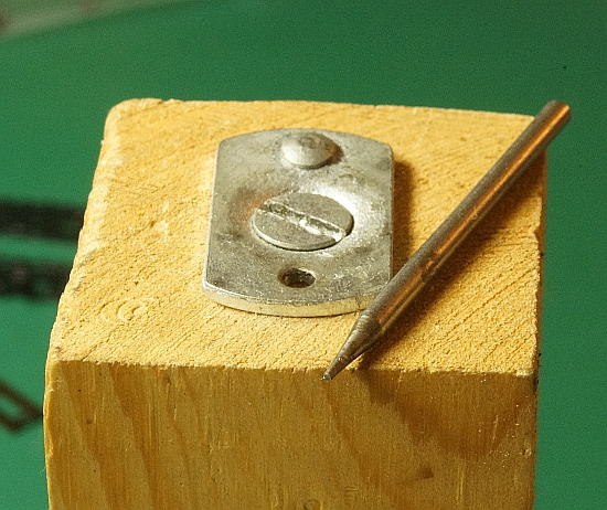
Just line up the pin or shaft over the little hole and tap it out. If the pin or shaft falls down in the hole, it does not get trapped. Just turn the block over and it will fall out since the hole in the wood is the same size as the hole in the metal.
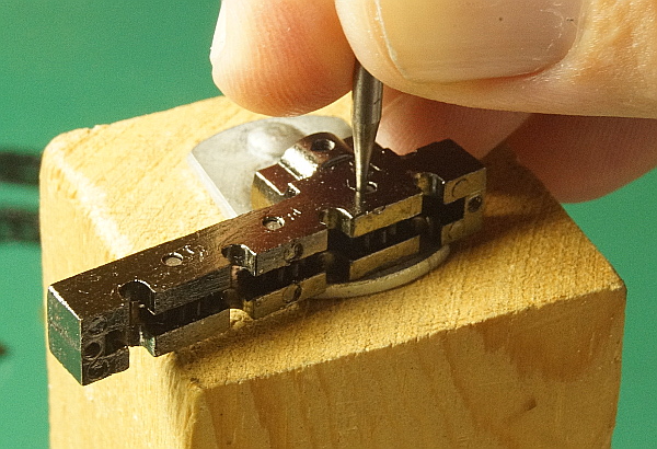
OK. The first pin has been beaten gently. I can now pull it out with my fingers and get the gear out.
Two more to go.
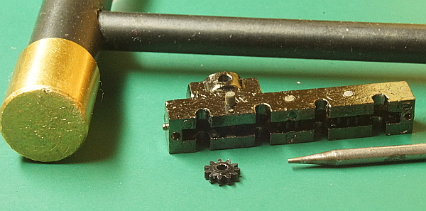
Now I am down to the bare gearcase frame.
One other thing to notice that Kumata did on this new model is chrome plate the Zamac metal.
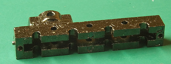
Now time to get to work on the mods for this truck.