Author Topic: Next18 Pin Outs...  (Read 884 times)

0 Members and 1 Guest are viewing this topic.

Sumner

  • Crew
  • *
  • Posts: 360
  • Gender: Male
  • Respect: +767
    • My Home Pages....
Next18 Pin Outs...
« on: June 06, 2022, 11:02:32 AM »
0
I could use some help on understanding some of the Next18 pin outs and this Lais Adapter Board.
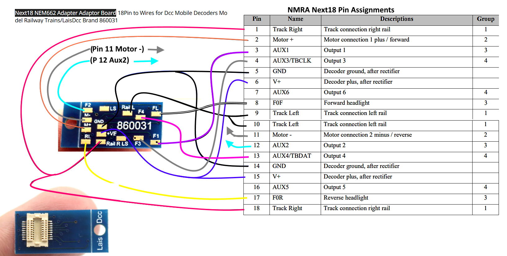


1.  Wondering if I have the pads on the adapter linked to their corresponding outputs?

2.  Are the two pads that are marked 'LS' for logic signal outputs?  If so I'm wonder how one would know which is which except by trial and error?

3.  A decoder I'm looking at has the Aux 3 and 4 outputs as logic outputs.  Do you think I'd find those outputs on F3 and F4 or on the two pads marked LS?

4.  Is AUX6 (pin 7) one LS pad and AUX5 (pin 16) the other one.

5.  What is the meaning of AUX3/TBCLK (Pin 4) and AUX4/TBDAT? I saw something somewhere about a decoder that had serial output??

Thanks for any help with this,

Sumner


Working in N Scale ---Modeling UP from late 40's to early 70's very loosely......

Under$8.00 Servo turnout Control --- 3D Printed Model RR Objects -- My Home Page

http://1fatgmc.com/RailRoad/RR Main/Link Page Menu.html

wvgca

  • Crew
  • *
  • Posts: 320
  • Respect: +44
Re: Next18 Pin Outs...
« Reply #1 on: June 06, 2022, 11:06:20 AM »
+1
i have a bunch of Lais decoder boards, [complete with stay alive], but none of the 18 pin adapters, sorry

peteski

  • Crew
  • *
  • Posts: 32969
  • Gender: Male
  • Honorary Resident Curmudgeon
  • Respect: +5345
    • Coming (not so) soon...
Re: Next18 Pin Outs...
« Reply #2 on: June 06, 2022, 12:29:35 PM »
+2
If you have a multimeter (with either ohm range or even better, continuity tester feature), simply put one lead on the LS pads and using the other lead probe all the Next18 pins to to figure out where that LS pad is connected.  You might have to use something sharp (like a straight pin or a sewing needle attached to the probe of one of the meter's test leads) to improvise a sharp probe for checking the Next18 connector.


I do lots of miniature electronic work so  I made a pair of fine test leads using needles, with a handles made of thin white styrene tube, and leads made from ESU decoder wires.  The other ends of the leads have alligator clips, so I can clip them to the standard multimeter leads.
« Last Edit: June 06, 2022, 12:34:32 PM by peteski »
. . . 42 . . .

Sumner

  • Crew
  • *
  • Posts: 360
  • Gender: Male
  • Respect: +767
    • My Home Pages....
Re: Next18 Pin Outs...
« Reply #3 on: June 06, 2022, 07:38:55 PM »
0
Thanks I'll double check things with the multimeter.

I found some answers to one of my other questions but don't think I totally understand it....

5.  What is the meaning of AUX3/TBCLK (Pin 4) and AUX4/TBDAT? I saw something somewhere about a decoder that had serial output??

Quote
Group 4 Outputs are defined as TTL/LVTTL logic-level according to Table 2 below. Maximum load 0.5 mA. If Train Bus is supported, the decoder must include a 470Ω
series resistor on AUX3/TBCLK (pin 4) and AUX4/TBDAT (pin 13), and must have 15KΩ (or greater) pull-up on TBDAT (pin 13) before the 470Ω series resistor.
95 During startup, these decoder outputs may be briefly undefined. If this brief undefined state is critical to the system board operation, then precautions should be
implemented on the system board. (AUX5/AUX6 NEXT18 only).

So I have to figure out for sure which pads those are going to if I'm going to use them (multimeter time).  I have some of the SBS4DCC Aux 3-4 Logic Level Function Amplifier Boards ( https://store.sbs4dcc.com/SBS4DCCAux3-4LogicLevelFunctionAmplifierBoard.aspx ). If I use one of those on the logic outputs along with dropping resistors for LEDs could I forgo all of what they are talking about in the 'Group 4 Outputs" above?

I can get the Next18 adapters for a little over $4 and a 6 function decoder for about $18 so might try that combination on a loco.

Sumner

« Last Edit: June 06, 2022, 07:41:30 PM by Sumner »
Working in N Scale ---Modeling UP from late 40's to early 70's very loosely......

Under$8.00 Servo turnout Control --- 3D Printed Model RR Objects -- My Home Page

http://1fatgmc.com/RailRoad/RR Main/Link Page Menu.html

peteski

  • Crew
  • *
  • Posts: 32969
  • Gender: Male
  • Honorary Resident Curmudgeon
  • Respect: +5345
    • Coming (not so) soon...
Re: Next18 Pin Outs...
« Reply #4 on: June 06, 2022, 07:48:33 PM »
+1
Yes, those pads are most likely connected to AUX5 and AUX 6 on the Next18 connector.  It will be good to double check with the multimeter.

Before you invest in the amplifier circuit or worry about all that pull-up resistor stuff check if the decoder you are using already has those AUX outputs as standard (high power) functions.  If that is the case, then you won't need the amplifier.
. . . 42 . . .

Sumner

  • Crew
  • *
  • Posts: 360
  • Gender: Male
  • Respect: +767
    • My Home Pages....
Re: Next18 Pin Outs...
« Reply #5 on: June 06, 2022, 08:47:39 PM »
0
Thanks, I already got a couple for possible use with some Loksound decoders I have but might not need those outputs,

Sumner
Working in N Scale ---Modeling UP from late 40's to early 70's very loosely......

Under$8.00 Servo turnout Control --- 3D Printed Model RR Objects -- My Home Page

http://1fatgmc.com/RailRoad/RR Main/Link Page Menu.html

reinhardtjh

  • Crew
  • *
  • Posts: 3006
  • Respect: +365
Re: Next18 Pin Outs...
« Reply #6 on: June 06, 2022, 10:15:02 PM »
+1
Since no polarity is indicated on the two "LS" contacts, it could very well be Loud Speaker . I don't see any other pads marked and the Next18 should have two connections for a speaker somewhere.
John H. Reinhardt
PRRT&HS #8909
C&O HS #11530
N-Trak #7566

Sumner

  • Crew
  • *
  • Posts: 360
  • Gender: Male
  • Respect: +767
    • My Home Pages....
Re: Next18 Pin Outs...
« Reply #7 on: June 06, 2022, 11:36:15 PM »
0
Since no polarity is indicated on the two "LS" contacts, it could very well be Loud Speaker . I don't see any other pads marked and the Next18 should have two connections for a speaker somewhere.

You are right.  Upon further reading one of the LS pads is connected to pin 7 and the other to pin 16.  With a non-sound decoder they are AUX 6 and AUX 5.  With a sound decoder they become the Speaker B and Speaker A.

https://www.nmra.org/sites/default/files/standards/sandrp/pdf/s-9.1.1.5_next18_next18-s_decoder_interface.pdf

Sumner
Working in N Scale ---Modeling UP from late 40's to early 70's very loosely......

Under$8.00 Servo turnout Control --- 3D Printed Model RR Objects -- My Home Page

http://1fatgmc.com/RailRoad/RR Main/Link Page Menu.html